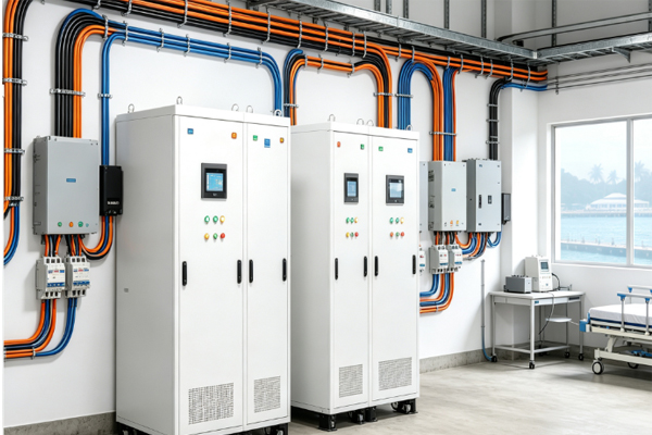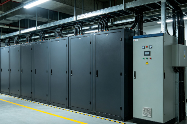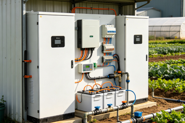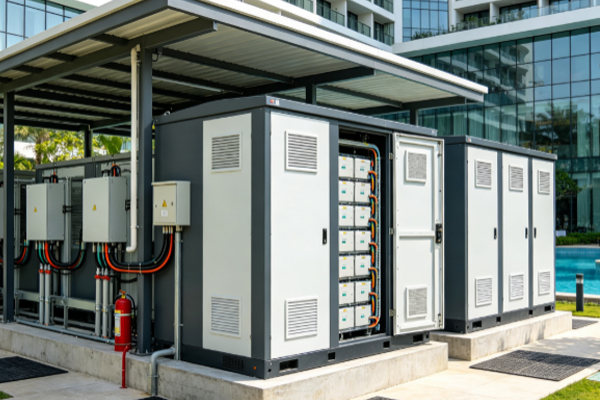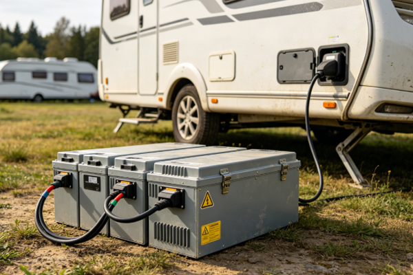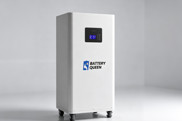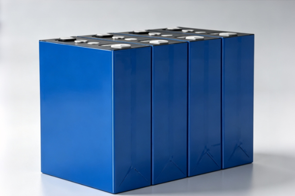
The DELIGREEN 24V 314Ah LiFePO4 Energy Storage Battery DIY Kit is a modular, standard battery assembly solution designed for home energy storage, RV, marine, off-grid solar, and small commercial backup power applications. The kit uses 8 series-connected 3.2V/314Ah high-capacity prismatic LiFePO4 cells (8S configuration), delivering a nominal system voltage of 25.6V and a total storage capacity of approximately 7.99kWh. It integrates a smart BMS protection board, a touchscreen LCD display, a DC circuit breaker, and a full set of insulation and protective components. Users can assemble the pack following the provided procedure and put it into service after completing the APP calibration.
Kit Contents
Metal cabinet housing (including front panel, top cover, and brackets)
Dual PCB cell voltage-sensing boards (8S specific)
Industrial-grade BMS protection board (with pre-assembled wiring harness)
LCD touchscreen display (with strong adhesive backing on the rear)
Yellow epoxy insulation boards + EVA foam
Copper busbars, copper terminals, and bolts
DC circuit breaker, heavy-duty positive/negative output terminals
Multi-core sensing wires, temperature sensor wire, and communication ribbon cables
Insulation caps, wiring harnesses, and fasteners
Key Technical Specifications
Cell: 3.2V/314Ah prismatic LiFePO4
Configuration: 8S series
Nominal voltage: 25.6V
Nominal capacity: 314Ah (BMS factory default is 200Ah — must be calibrated via APP)
Stored energy: approx. 7.99kWh
Communication interfaces: RS485 ×2, CAN, RS232, UART
Tightening torque: 7.5 N·m
Cycle life: 6,000+ deep cycles
II. Installation Procedure (13 Steps)
1. Unboxing & Inventory Check Remove the top cover, front panel, and brackets. Take out all components and inspect the PCBs, cables, and structural parts for scratches or broken wires.
2. Install Epoxy Insulation Boards Install the boards onto the inner walls and partition panels of the cabinet. They serve as the primary insulation layer between the cells and the metal enclosure.
3. Cell Arrangement & Foam Insertion Place the 8 cells into the compartments according to the numbering marked on the PCB. Stick two strips of EVA foam onto each epoxy board and insert them between adjacent cells. Align the polarity by referencing the “Cell 1 / Main Negative” marking on the left PCB.
4. Install Front Partition Panel Tighten the screws to secure the cells and prevent shifting during transport or vibration.
5. Install the Dual PCB Sensing Boards Apply foam to the bottom for insulation, then mount and tighten the boards. Each sensing point must correspond one-to-one to the positive/negative terminals of its respective cell.
6. Connect Copper Busbars & Route Sensing Wires Connect the busbars in series to form the 8S circuit. Do NOT connect the main positive/negative terminals at this stage. Connect each sensing wire to its matching terminal one-to-one, and attach the temperature sensor wire to the main negative terminal.
7. Standardize Torque After pre-tightening with an electric screwdriver, re-tighten all bolts to 7.5 N·m using a digital torque wrench.
8. Install the LCD Display The adhesive backing is very strong — never install it upside down (otherwise the display will be inverted and very difficult to remove once stuck). Align the display with the cutout and press evenly.
9. Install BMS / Circuit Breaker / Communication Sub-board Connect one end of the circuit breaker to the positive output terminal. Secure the black main negative wire to the negative terminal post. Plug in the communication ribbon cables according to their labels.
10. Install the Front Panel Assembly Reattach the cabinet body and tighten all screws.
11. Connect the Main Power Cables (Strictly Negative First, Then Positive) First connect the thick black main negative cable (BMS P− → Cell 1 main negative). Then connect the thick red main positive cable (BMS B+ → positive terminal of the last cell), and at the same time connect the small red B+ auxiliary sensing wire.
12. Plug Sensing Ribbon Cables into the BMS Left PCB ribbon cable → white terminal slot; right PCB ribbon cable → purple terminal slot.
13. Power-On Testing & APP Calibration Connect via Bluetooth to the APP. Set the series count to 8S and the capacity to 314Ah (the factory default of 200Ah must be updated). Verify cell voltage balance, temperature, and protection thresholds before putting the system into service.
Key Cautions
The main circuit must be connected LAST, after the sensing wires and busbars are complete — always negative first, then positive.
The LCD adhesive must be aligned correctly on the first attempt.
All bolts must be uniformly tightened to 7.5 N·m.
Re-check the wiring order and polarity before powering on.
After-Sales Support
If you encounter any difficulty during assembly, contact our customer service — we will respond within 12 hours with a professional solution.