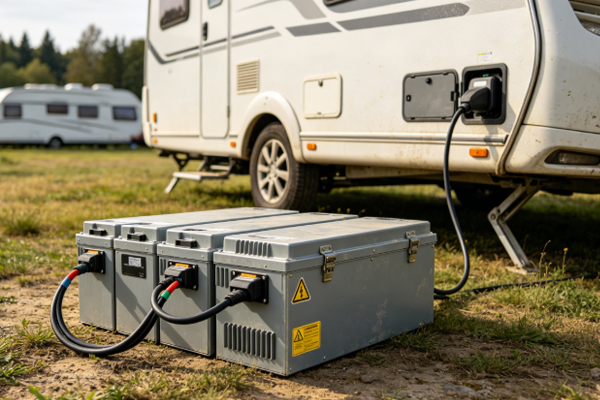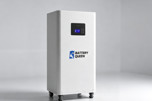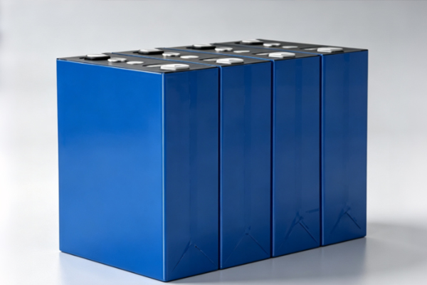
The DELIGREEN 12V 628Ah LiFePO4 Energy Storage Battery DIY Kit is designed for RV / campervan, marine, home backup power, off-grid solar, and small commercial applications. The kit uses 4 series-connected 3.2V/628Ah high-capacity prismatic LiFePO4 cells (4S configuration), delivering a nominal system voltage of 12.8V (commonly referred to as 12V) and a total storage capacity of approximately 8.04kWh. It integrates a smart JK BMS protection board, an LCD display, a central balancing PCB, DC fuses, and a full set of insulation and protective components. The system is ready for use after APP calibration.
Product Advantages
① Large capacity with fewer series/parallel connections — 4S achieves approx. 8kWh with fewer connection points and simpler assembly ② Layered insulation design — dual insulation of epoxy boards + EVA foam absorbs vibration and isolates heat transfer ③ Central balancing and per-cell monitoring ④ Standardized 8 N·m torque control ⑤ Integrated smart management — LCD, fuse, NTC, and JK APP remote parameter adjustment
Application Scenarios
RV / campervan power supply
Marine energy storage
Home backup power
Off-grid solar storage
Small commercial backup power
Remote construction site power supply
Installation Procedure
Step 1 — Enclosure Preparation Line the inside of the enclosure fully with epoxy insulation boards.
Step 2 — Install the 4 Cells (628Ah) Arrange the cells to form a 4S series configuration, paying attention to cell orientation and polarity.
Step 3 — Insert EVA Foam Epoxy Strips Insert between adjacent cells to absorb vibration and isolate heat transfer.
Step 4 — Install the Front Panel & Prepare the BMS Hardware
Step 5 — Install the Central Balancing PCB & Connect the Cell Busbars (4S series)
Step 6 — Connect the Sensing Harness & NTC Temperature Sensor Connect the NTC wire to the negative terminal. Do NOT connect the battery positive/negative terminals at this stage.
Step 7 — Standardize Torque & Install the Fuse After tightening all screws, re-tighten uniformly to 8 N·m. Install the fuse on the right side as shown in the diagram.
Step 8 — Connect the Main Positive Terminal
Step 9 — Connect the Main Negative Terminal
Step 10 — Connect the LCD Cable, Communication Cable, and ON/OFF Switch Cable
Step 11 — Close the Front Panel
Step 12 — Connect BMS P− to the Battery Main Negative
Step 13 — Connect BMS P+ to the Battery Main Positive
Step 14 — Plug the Voltage Sensing Cables into the Protection Board Align the connectors carefully when plugging in to avoid damaging the PCB.
Power-On Debugging & APP Calibration After powering on, connect the JK APP (login password: 1234; parameter authorization password default: 123456), configure 4S + 628Ah, verify cell voltage balance and temperature, then close the top cover and put the system into service.
Key Cautions
The main positive/negative terminals must be connected LAST and strictly follow the step order.
All bolts must be uniformly tightened to 8 N·m.
The NTC must be connected to the negative terminal.
Align the sensing cable connectors properly when plugging in.
Re-check the wiring order and polarity before powering on.
After-Sales Support
If you encounter any difficulty during assembly, contact our customer service — we will respond within 8–12 hours with a professional solution.