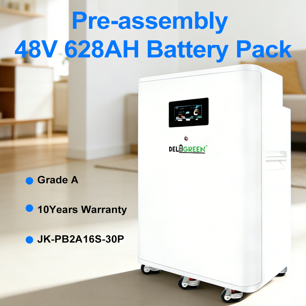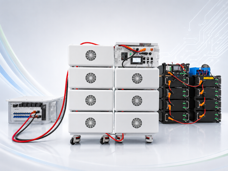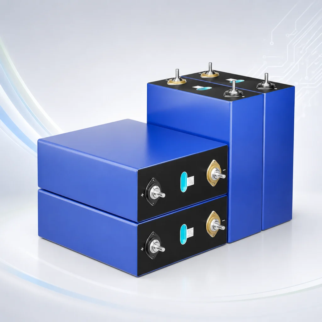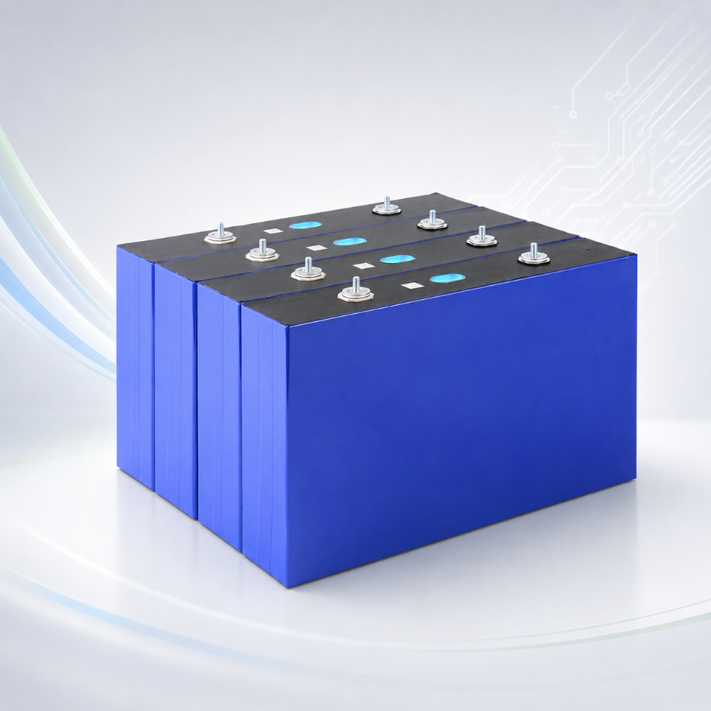
A battery pack contains multiple cells, connecting tabs, wiring harnesses, and protection circuits. Reliable isolation must be maintained between different conductive components. Improper insulation design may cause leakage, short circuits, and localized overheating, and in severe cases may affect the operational safety of the battery pack. Therefore, the design should comprehensively consider the voltage level, structural layout, operating temperature, vibration environment, and long-term operating conditions.
Insulation Materials Must Be Suitable for the Operating Environment
The internal space of a battery pack is limited. Insulation materials must not only have good electrical properties but also be able to withstand thermal, mechanical, and chemical conditions.
Focus on the Insulation Performance of Materials
Different locations perform different insulation functions, so material selection should be based on the specific structure:
- Dielectric strength: The material must meet the isolation requirements under the corresponding operating voltage.
- Temperature resistance: The insulation material should remain stable after heat is generated during charging and discharging.
- Aging resistance: The material should not experience obvious embrittlement, cracking, or performance degradation after long-term use.
Suitable insulation materials can provide continuous protection for cells and conductive components.
Consider Both Flame Retardancy and Mechanical Properties
During transportation, assembly, and operation, the battery pack may be subjected to vibration, impact, or compression. Therefore, insulation materials should have a certain level of mechanical stability. For products with higher safety requirements, flame-retardant materials should also be selected, and their compatibility with the electrolyte and structural components should be confirmed.
Battery Pack Structural Design Must Ensure Reliable Isolation
Insulation design cannot rely solely on a single layer of insulating film. The arrangement of cells, the positions of connecting tabs, and the enclosure structure must all provide reasonable isolation space.
Control the Distance Between Conductive Components
Metal components with different potentials should maintain a reasonable distance to reduce the risk of accidental contact.
- Between cells: Add necessary isolation layers according to the structure.
- Between connecting tabs and the enclosure: Prevent metal connectors from directly contacting the enclosure.
- Between the positive and negative electrode areas: Provide focused protection for high-risk locations.
Reasonable structural spacing can reduce the risk of short circuits caused by assembly deviations.
Reduce Insulation Damage Caused by Sharp Edges and Burrs
Burrs on metal connectors, brackets, and enclosure edges may wear through the insulation layer during long-term vibration. The edge structure should be optimized during design, and protective measures should be added in areas prone to friction. Areas such as cable openings and connecting-tab edges should also be designed to prevent continuous compression of the insulation material.
Connection Areas Are a Key Focus of Insulation Design
Welded joints, busbars, wiring harnesses, and terminals are concentrated in connection areas and require targeted insulation treatment.
Strengthen Protection Around Tabs and Busbars
Connection areas contain many exposed conductive components. Insulation design must balance electrical isolation with heat dissipation space.
- Cover exposed metal areas: Reduce the possibility of conductive components coming into contact with other structures.
- Protect welded areas: Prevent the edges of welds from puncturing the insulation material.
- Treat high-potential areas: Provide targeted isolation for positive and negative terminal connections.
Complete insulation measures in connection areas can reduce accidental conduction during assembly and use.
Consider Wiring Harness Fixation and Insulation Together
Wiring harnesses may suffer outer-sheath damage after prolonged pulling, friction, or bending. The wiring path should be properly planned during design, and fixing structures should be used to reduce movement. Protective sleeves or other isolation structures should also be installed where wiring harnesses pass through the enclosure to reduce the risk of wear.
Insulation Testing and Long-Term Reliability Must Not Be Overlooked
After the battery pack is assembled, the effectiveness of the insulation design should be verified through testing rather than relying solely on visual inspection.
Establish Necessary Insulation Testing Procedures
During battery pack production, corresponding inspection items can be established according to the product structure and applicable standards:
- Insulation resistance testing: Check the insulation condition between conductive parts and the enclosure or other specified areas.
- Withstand voltage testing: Verify the withstand capability of the insulation system according to the product design and applicable standards.
- Visual inspection: Check whether the insulating film, isolation sheets, and wiring harness sheaths have damage, displacement, or other defects.
Multiple inspection methods can provide a more comprehensive verification of the integrity of the insulation structure.
Monitor Insulation Conditions After Long-Term Use
After long-term charge and discharge cycles, temperature changes, vibration, and material aging may all affect insulation performance. During maintenance, check the connection areas, wiring harnesses, insulation sheets, and the inside of the enclosure for wear, deformation, or looseness. If damaged insulation, displaced conductive components, or abnormal heating is found, stop using the battery pack and have it handled by qualified professionals.
Battery pack insulation design must also be verified in combination with actual manufacturing processes and subsequent operating conditions. During assembly, the positional accuracy of insulation components should be controlled to prevent misalignment, compression, or wear from affecting isolation performance. After the battery pack is put into use, the condition of the insulation layers, wiring harnesses, and connection points should be checked regularly, and issues such as aging and looseness should be addressed promptly to ensure that insulation performance remains stable over the long term.