During long-term use, an increase in internal resistance can lead to reduced capacity, insufficient output power, increased heat generation, and shorter runtime. In severe cases, it may also affect the safety and service life of the entire battery pack. For new energy vehicles, energy storage systems, power tools, and backup power supplies, reducing the impact of internal resistance requires more than focusing on the cells themselves. Optimization should also cover cell consistency, connection structures, charge and discharge management, temperature control, inspection, and maintenance. Only when all these aspects work together can the operating condition of the battery pack be improved.
Reduce Internal Resistance Differences by Improving Cell Consistency
A battery pack consists of multiple cells connected in series or parallel. Differences in internal resistance between individual cells can be amplified and become a major cause of declining pack performance. Cell screening and matching are the foundation for controlling the impact of internal resistance.
Select Cells with Similar Internal Resistance
When purchasing and using cells, pay close attention to the following aspects:
- Check parameters such as cell capacity, internal resistance, voltage platform, and self-discharge rate.
- Conduct capacity grading tests and internal resistance screening.
- Avoid mixing new and used cells.
- Do not combine cells from different brands or models without proper evaluation.
- Retest cells after long-term storage.
- Remove cells with abnormal appearance, low capacity, or significantly high internal resistance.
Cells with similar internal resistance can reduce voltage deviations during operation and help distribute the load more evenly across the battery pack.
Perform Proper Cell Matching
Cell matching should not be based solely on rated capacity. Test data should also be taken into account:
- Group cells with similar capacities together.
- Select cells with small differences in internal resistance.
- Check voltage consistency when connecting cells in series.
- Check internal resistance and current distribution when connecting cells in parallel.
- Conduct charge and discharge tests on the battery pack.
- Record cell-matching data for future maintenance.
Cells with similar capacities but significantly different internal resistance will experience different voltage drops during high-current discharge. By comprehensively comparing capacity, internal resistance, and voltage consistency, the impact of individual cells on overall pack performance can be reduced.
Optimize the Connection Structure and Current Transmission Paths
In addition to the internal resistance of the cells themselves, nickel strips, busbars, connectors, weld points, and wiring harnesses also create additional resistance and affect the overall performance of the battery pack. Therefore, the connection structure and current paths also require careful optimization.
Reduce Contact Resistance at Connection Points
The connection structure should shorten the current path as much as possible while maintaining stable contact:
- Select connection materials with good electrical conductivity.
- Increase the conductive cross-sectional area at key locations according to the operating current.
- Control welding quality to reduce cold solder joints, missed welds, and overheated weld points.
- Keep contact surfaces clean and prevent oxides and impurities from affecting conductivity.
- Regularly check whether bolts, terminals, and connectors are loose.
- Promptly address connection points showing discoloration, burning, or abnormal heating.
Reducing connection resistance can lower voltage drop and heat generation when the battery pack operates at high current.
Improve Busbar and Wiring Harness Design
Uneven current distribution inside the battery pack may cause some cells to bear higher loads for extended periods. The following aspects should be considered during design optimization:
- Plan the busbar layout properly.
- Keep wiring harnesses as short as possible.
- Reduce unnecessary adapters and connection points.
- Keep the positive and negative lead-out paths as symmetrical as possible.
- Check impedance differences between parallel branches.
- Prevent certain branches from carrying excessive current because their paths are too short or too long.
- Select wiring harnesses and connectors with suitable specifications according to the maximum operating current.
Proper current paths help improve current distribution and reduce localized temperature rise.
Strengthen Insulation and Structural Fixation
After prolonged exposure to vibration, impact, or thermal expansion and contraction, connection points in a battery pack may become loose or develop poor contact. The following points should be considered during structural design and assembly:
- Use reliable insulating materials to isolate energized components.
- Adopt sturdy mounting brackets and compression structures.
- Add cushioning and anti-loosening measures in areas prone to vibration.
- Prevent cells from being squeezed, rubbed against each other, or displaced.
- Regularly check whether connectors, brackets, and housings are loose.
- Inspect long-term operating equipment for structural changes caused by thermal expansion and contraction.
Stable assembly quality can reduce fluctuations in contact resistance caused by mechanical changes.
Control the Increase in Internal Resistance Through Charge, Discharge, and Thermal Management
Operating conditions affect cell polarization, material aging, and interface stability. Proper charge, discharge, and temperature management can help slow the increase in internal resistance.
Control Charge and Discharge Rates
High-rate charging and discharging increase internal polarization and heat accumulation. Pay attention to the following points during use:
- Set an appropriate charging current according to the cell specifications.
- Avoid long-term overload discharge.
- Apply staged current control to fast-charging equipment.
- Reduce high-power output when the battery is at a low state of charge.
- Dynamically adjust charge and discharge power according to battery temperature.
- Avoid continuing high-rate operation when the cells are in an abnormal condition.
Moderate charge and discharge rates can reduce cell stress and slow performance degradation.
Avoid Operation at Extreme Temperatures
High temperatures accelerate side reactions, while low temperatures reduce electrolyte conductivity and cause a temporary increase in internal resistance. The following measures should be implemented during actual use:
- Equip the battery pack with an appropriate heat dissipation structure.
- Add insulation or preheating measures in low-temperature environments.
- Monitor key cell locations using temperature sensors.
- Avoid directly charging at high current when the battery is at a low temperature.
- Reduce power or suspend operation promptly when the battery is at a high temperature.
- Minimize long-term exposure of the battery pack to high temperatures, low temperatures, or environments with large temperature differences.
Maintaining a suitable temperature range helps preserve the normal power output of the battery pack.
Optimize BMS Protection Parameters
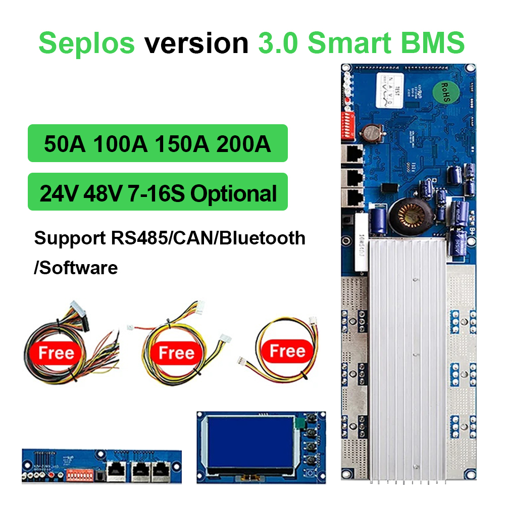
The BMS should set protection thresholds according to the cell type, the number of series and parallel connections, and the application scenario. Key functions include:
- Monitoring changes in individual cell voltage and temperature.
- Identifying abnormal voltage drops and internal resistance differences.
- Controlling the risks of overcharging, over-discharging, overcurrent, and short circuits.
- Adjusting charge and discharge power according to temperature changes.
- Reducing differences in individual cell conditions through balancing functions.
- Setting alarms, current limits, or disconnect protection for abnormal cells.
- Regularly checking whether BMS sampling wires and sensors are functioning properly.
A properly configured BMS can reduce damage to cells under abnormal operating conditions and prevent differences between individual cells from becoming more severe.
Establish Inspection, Maintenance, and Life-Cycle Management Mechanisms
Internal resistance problems usually develop gradually. Regular inspections help identify abnormalities at an early stage and prevent sudden declines in battery pack performance. A complete maintenance system should cover inspection, evaluation, corrective action, and recordkeeping.
Regularly Check Internal Resistance and Voltage Differences
During inspection, do not check only the total pack voltage. Also monitor individual cell voltage, internal resistance, temperature, and voltage drop under load. Comparing cells under the same state of charge and similar temperature conditions makes it easier to identify abnormal cells. Cells with significantly high internal resistance or excessive voltage drop under load should be retested or replaced promptly. Continuous data recording helps determine the aging trend of the battery pack.
Address Abnormal Cells Promptly
When the internal resistance of one cell is significantly higher than that of the other cells, continued use may cause the entire pack to overheat and limit its capacity. Pay attention to the following points during handling:
- Evaluate the actual condition of the cell together with capacity test results.
- Check whether the cell has swelling, leakage, or physical damage.
- Observe the temperature rise of the abnormal cell under load.
- Determine whether the problem is caused by cell aging or poor connection.
- Replace the cell with one having similar parameters.
- Perform cell matching and balancing again after replacement.
- Avoid directly mixing new and used cells.
Promptly addressing abnormal individual cells can prevent localized faults from further affecting other cells.
Develop Life-Cycle Strategies According to the Application Scenario
New energy vehicles, energy storage systems, and power tools have different operating loads, so their internal resistance management methods should also differ:
- New energy vehicles should focus on controlling fast-charging rates, peak power, and operation at high and low temperatures.
- Energy storage equipment should focus on long-term operating temperature, balancing performance, and regular inspection.
- Power tools should focus on controlling instantaneous high-current output and heat dissipation conditions.
- Backup power supplies should pay attention to changes in capacity, internal resistance, and self-discharge after long-term storage.
- High-load equipment should have shorter inspection intervals to identify abnormal voltage drops and temperature rises promptly.
- Long-term operating equipment should maintain complete operating data and maintenance records.
Developing management plans according to actual load, environmental conditions, and operating cycles can improve the effectiveness of internal resistance monitoring.
The key to managing battery pack internal resistance is to reduce differences between individual cells, minimize connection losses, and limit unfavorable operating conditions such as high-rate operation and extreme temperatures. Through proper cell matching, optimized conductive structures, improved BMS parameters, and regular inspection systems, abnormalities such as voltage drop, temperature rise, and performance degradation can be identified promptly. Different applications should also adopt corresponding strategies based on their load characteristics and maintenance conditions, thereby improving the reliability and maintainability of battery pack operation.