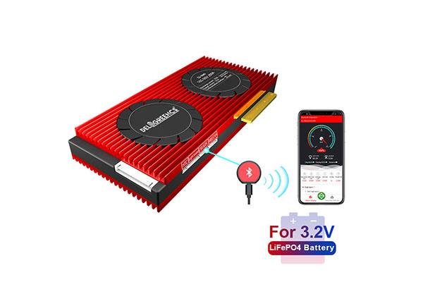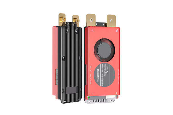
A Battery Management System (BMS) is a key control unit in a lithium battery pack. It monitors cell conditions, manages charging and discharging, and implements protection strategies when abnormal conditions occur. For battery pack designers, understanding common BMS terms helps with cell selection, electrical parameter matching, protection scheme design, and system integration.
In residential energy storage, commercial and industrial energy storage, and industrial power supply projects, BMS parameters affect not only battery performance but also system compatibility and safety. Understanding the following core concepts helps designers interpret technical specifications more accurately.

Common BMS Terms for Battery State Monitoring
SOC: State of Charge
SOC (State of Charge) represents the estimated remaining charge in a battery as a percentage of its available capacity. For example, an SOC of 80% indicates that the battery’s estimated charge level is 80%.
SOC is not a direct measurement of the remaining energy. Instead, the BMS estimates it using current, voltage, temperature, and battery models. Designers should consider SOC estimation accuracy and performance under different load and temperature conditions.
SOH: State of Health
SOH (State of Health) describes the battery’s health relative to its initial condition. It is commonly associated with capacity degradation and changes in internal resistance. Different manufacturers may use different methods to calculate SOH, so designers should confirm its definition and calculation basis when comparing BMS products.
SOC focuses on the battery’s current charge level, while SOH reflects long-term performance changes. These two terms should not be used interchangeably.
SOF: State of Function
SOF (State of Function) evaluates how much power a battery can deliver or accept under current operating conditions. It is generally influenced by SOC, SOH, temperature, voltage limits, and current limits.
For energy storage systems that must respond to sudden load changes, SOF information helps determine whether the battery can meet current power demands.
BMS Electrical Parameters and Protection Terms
Overvoltage and Undervoltage Protection
Overvoltage protection prevents the voltage of an individual cell or the entire battery pack from exceeding the specified upper limit. Undervoltage protection prevents voltage from falling below the permitted lower limit. Designers must distinguish between individual cell protection thresholds and total battery pack thresholds, setting parameters according to the cell manufacturer’s specifications.
Different lithium battery chemistries have different voltage ranges, so the same protection parameters should not be applied indiscriminately to every battery type.
Overcurrent and Short-Circuit Protection
Overcurrent protection responds when charging or discharging current exceeds a predefined limit. Short-circuit protection addresses abnormally high currents caused by short circuits and generally requires rapid detection and interruption mechanisms.
During the design process, engineers should verify the BMS continuous current rating, peak current rating, protection response time, and the rated specifications of contactors, fuses, and cables. This helps ensure that the overall protection system meets application requirements.
Temperature Protection
Temperature protection uses sensors to monitor the operating conditions of individual cells or the battery pack. When temperatures exceed the permitted range, the BMS can limit charging and discharging or stop the relevant operation.
Designers should also consider sensor placement, heat distribution, and ambient temperature to ensure that monitoring data accurately reflects actual battery conditions.
BMS Balancing and Communication Terms
Passive Balancing vs. Active Balancing
Passive balancing typically uses resistors to dissipate some of the excess energy from cells with higher charge levels, helping reduce voltage differences between cells. Active balancing transfers energy from certain cells to others through dedicated circuits.
Passive balancing generally has a simpler structure, while active balancing focuses on energy transfer efficiency. The appropriate solution depends on battery pack capacity, cell consistency, cost, and operating conditions.
CAN and RS485 Communication
CAN and RS485 are common communication interfaces in battery systems. CAN is frequently used for data exchange between the BMS, inverters, and controllers, while RS485 is widely used in energy storage equipment and industrial monitoring systems.
However, using the same interface does not guarantee protocol compatibility. Designers should also verify the baud rate, data format, register definitions, and communication protocol version to ensure reliable integration.
How to Apply BMS Terminology to Battery Pack Design
During battery pack design, engineers should define BMS monitoring and protection requirements based on cell chemistry, series and parallel configuration, rated voltage, capacity, continuous and peak current, operating temperature, and intended application. Compatibility between the BMS and inverters, charging equipment, and host computers should also be confirmed.
DeliGreen provides LiFePO4 cells, battery packs, BMS products, and related energy storage solutions. Battery parameters and system configurations can be evaluated according to project requirements. For customized battery projects, clarifying key terms such as SOC, SOH, protection thresholds, balancing methods, and communication protocols early in the design process helps reduce design inconsistencies, improve system integration efficiency, and support reliable battery operation.